Drivers in “O” scale are almost impossible to find. And when a set is found it must be machined to Proto 48 standards. This means new tires and the wheel casting must be thinned to be more prototype. Or, build your own.
Many years ago Precision Scale had extra 63″ drivers that were for their SP cab forward import. I bought enough for a Burlington 2-8-2 and a 2-10-4. That was the learning process for working with redoing drivers to P48 standards and reassemble with the proper 90-degree quarter between left and right sides. I built a quartering tool to do this. Often, to be prototype, new counter weights and even centers have to be fabricated and soldered on before assembling as I did with the 2-10-4.
I have several projects going at the present time, two of which are a 4-8-2 with 74″ drivers and a 2-6-2 needing 69″. These are not available on the market, that I know of anyway. Through the years I have admired the work of Louis Bartig and with some of his later models he handmade the drivers.
Wonder if I could do that?
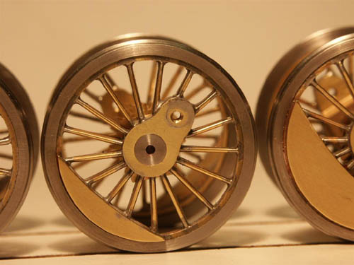
So a new project was started. I have just finished a set of the 74″ for a CB&Q B1 mountain and it was a real learning process! I have many component drawings of this engine, including the drivers. So first I machined the outside wheel rims from brass bar stock and then the counter weights, to exact scale. The hub cranks were made with the hub for the heavy counter weight wheels slightly larger as per prototype.
These drivers had 17 spokes that were not divisible with my Emco dividing tool. I had one old 81″ 17 spoke driver that I used as a pattern to mark off spoke positions on the end of a piece of aluminum bar. This bar was then machined to the inside diameter of the wheel rims. Then slots were cut with a slitting saw to hold the spokes for soldering


The completed set for the Mountain engine. The steel tires on this set are from Pat Mitchell. All the other tires on my engines were machined on my Emco lathe from stainless steel.

Right away you may be asking, “why not send one of the wheels as a pattern to a professional casting service?” Saves a lot of work. Actually I did that. The first model railroad parts caster said the spokes were too narrow and may not fill. So I sent the same pattern to another casting service. No response. Sent a letter asking “what about my pattern?” No response. That ended that.
This experience has shown that it is possible to build drivers so my next task will be to make those 69″ drivers for that CB&Q Prairie. The frame and cylinders have already been built.
I should let readers know that I am NOT a professional machinist. I learned this stuff when I bought a small Unimat SL back in about 1958 when I was a young sergeant of Marines. From that start it progressed to a Unimat 3, and now I have an Emco Compact 5 lathe. Also I have a milling machine. The point is, anyone can learn to machine, you just have to try. I have made a lot of mistakes over the years, and still do!


Leave a Reply